How to Wire a Pool Timer Box Safely

Wiring a pool timer means connecting incoming power wires to the input terminals and pump wires to the output terminals, after cutting all electricity at the breaker panel. The exact terminal pattern changes depending on whether the pump runs on 120 volts or 240 volts. All bare copper or green safety wires attach directly to the ground screw on the case. Keeping the incoming power separate from the pump wires protects the new timer from burning out the second power returns.
The right steps always depend on your equipment voltage and the type of timer box. A 120-volt circuit uses one live wire and a neutral wire, while a 240-volt circuit uses two live wires. Some digital models also rely on a small jumper wire that you must set for your voltage. Taking time to identify each wire first takes the stress out of making these connections safely.
Shutting Off Breaker Power and Confirming Zero Voltage
Working around a pool equipment pad means dealing with moisture, concrete, and heavy electrical current. Before you touch a single screw on your timer box, you must cut all electrical flow at the source. Flipping the manual switch on the front of the timer clock does not protect you. That switch only cuts power heading out to the pump motor, leaving the incoming terminals hot, live, and capable of causing severe injury.
- Find the dedicated pool subpanel or main circuit breaker: Look for the breaker labeled for your pool pump or pool equipment pad. If your pump runs on 240 volts, look for a double-pole breaker (two switch handles tied together with a plastic or metal bar).
- Switch the breaker completely off: Push the breaker handle firmly toward the off position until you feel a firm click. If the breaker panel is located out of sight from your pool pad, place a piece of tape or a lockout tag over the breaker switch so another household member does not turn it back on while you are working.
- Remove the protective timer deadfront: Open the timer door and unclip or unscrew the inner metal cover plate (often called the deadfront). This plate shields the bare screw terminals from accidental contact.
- Confirm zero voltage with a meter: Touch the probes of a digital multimeter or place a non-contact voltage detector against every single incoming wire, terminal screw, and metal surface inside the box. Measure voltage between both hot wires, between each hot wire and the neutral wire, and between each hot wire and the ground wire.
- Do not proceed until the meter reads zero: If you detect any voltage whatsoever, stop immediately. Double-check your breaker panel to locate the correct circuit switch before placing your hands near the wiring.
How to Identify Line Wires, Load Wires, and System Voltage
Wiring mistakes happen most often when people confuse incoming power wires with outgoing pump wires. To wire the box correctly, you need to sort your wires into two separate pathways: the supply coming from your electrical panel, and the feed going to your pump motor.
Line wires are the incoming wires carrying electricity directly from your circuit breaker panel into the timer box. They supply constant power to drive the internal clock motor and feed the switch.
Load wires are the outgoing wires carrying electricity from the timer box directly out to your pool pump motor. These wires only receive power when the timer pins or internal clock switch reach an active cycle.
Neutral wires are white return wires found in standard 120-volt circuits. The neutral wire carries electric current back to the panel to complete the circuit.
Ground wires are bare copper or green insulated safety wires. Ground wires never carry active current during normal operation. Instead, they provide a safe path directly into the earth if a loose wire touches the metal box or pump housing.
You also need to know whether your pool equipment pad runs on 120 volts or 240 volts. You can verify this by checking two places: your breaker box and the motor data label on the pump.
A 120-volt setup uses a single-pole breaker (a single switch handle), one hot wire (usually black), one white neutral wire, and one ground wire. A 240-volt setup uses a double-pole breaker (two handles joined together), two hot wires (usually one black and one red, or two black wires), and one ground wire. Many 240-volt pool pump motors do not require a neutral wire at all, although digital timers running on 240 volts sometimes require a neutral wire depending on the model.
Steps to Wire Line, Load, and Ground Terminals Correctly
Once you confirm the power is off and you know your system voltage, you can connect the wires to the terminal block. Standard mechanical pool timer boxes feature five numbered positions: terminal 1, terminal 2, terminal 3, terminal 4, and terminal A (used for neutral or clock motor feeds on certain models).
- Route wire conduits into the lower box knockouts: Push incoming line cables through one bottom knockout and outgoing load cables through another bottom knockout, securing both with threaded conduit connectors.
Reason: Using bottom openings prevents rain from trickling down into the wiring terminals, and tight fittings stop sharp metal edges from cutting into wire insulation. - Connect all green and bare copper wires to the ground bus: Insert every grounding wire into the green grounding terminal block at the bottom of the enclosure and tighten the screws firmly.
Reason: Bonding all safety grounds ensures that stray electrical current trips the breaker instantly instead of electrifying the metal timer cabinet. - Attach the neutral wire if your setup runs on 120 volts: In a 120-volt setup, connect the incoming white neutral wire from your breaker to terminal A or the designated neutral screw, then splice the pump neutral wire directly to it with a wire nut or connect it to the shared neutral terminal.
Reason: The white neutral wire completes the electrical circuit for a 120-volt pump and provides the return path required for the timer clock motor to tick. - Fasten the incoming line power wires to terminals 1 and 3: Strip about a half-inch of insulation from the incoming hot wires, loop them under the terminal screw clamps at position 1 and position 3, and tighten down firmly.
Reason: Terminals 1 and 3 supply uninterrupted power from your breaker panel to keep the timer clock mechanism spinning continuously throughout the day. - Fasten the outgoing load pump wires to terminals 2 and 4: Secure the wires leading out to your pool pump motor under the screw clamps at position 2 and position 4.
Reason: Terminals 2 and 4 only receive power when the timer switch closes, allowing the unit to control exactly when your pump turns on and off. - Check every connection with a firm tug: Gently pull each individual wire to make sure it is held tight under the screw clamp without slipping or shifting.
Reason: Loose electrical connections create high resistance, which causes excess heat, melted insulation, and sudden pump failure.
For a 240-volt installation, both incoming wires carry 120 volts of electricity (making 240 volts across both lines). You place line hot wire one into terminal 1, line hot wire two into terminal 3, pump load wire one into terminal 2, and pump load wire two into terminal 4. If your timer is a standard mechanical unit running on 240 volts, you generally do not connect any neutral wire to terminals 1 through 4.
Setting the Voltage Jumper and Sealing the Timer Box
Many modern pool timers are built to work with either 120 volts or 240 volts straight out of the box. To handle both, manufacturers install a voltage jumper (a short insulated wire or small metal clip on the back of the timer mechanism) that routes electricity to the small internal clock motor.
Before you close the box, check the wiring diagram printed inside the timer door to see where the jumper must point. If your system runs on 240 volts and you leave the jumper set for 120 volts, you will destroy the timer clock motor the moment you restore power. If your system runs on 120 volts and you leave the jumper set for 240 volts, the timer clock motor will not get enough power to advance the time dial, leaving your schedule frozen in place.
After confirming the jumper position, inspect the outer enclosure for weather protection:
- Use bottom knockouts only: Never punch out knockouts on the top or upper sides of an outdoor timer enclosure. Rain will eventually seep through upper conduit fittings and drip directly onto live wiring screws.
- Install conduit locknuts and bushings: Tighten the conduit locknuts until they bite into the metal housing to create a secure electrical bond, and screw plastic bushings over the conduit threads to keep wires from fraying.
- Seal unused openings: If an old knockout hole was left open during a previous installation, snap in an outdoor knockout seal or fill the gap with exterior silicone sealant. Open holes invite moisture, dirt daubers, and spiders, which love the warm space behind timer dials.
Steps to Restore Power and Check Pump Operation
Once your wiring is secure and the enclosure is sealed, follow these steps to verify your connections safely:
- Reinstall the interior protective cover: Screw the metal deadfront plate back into position over the terminal block.
Reason: The shield protects your hands from live electrical terminals while you reach inside to turn the dial or flip the manual switch. - Move the manual lever to the off position: Push the timer switch lever to off before restoring electrical flow.
Reason: Keeping the switch off prevents the pump from surging on instantly while you observe the timer box. - Switch the breaker on at the electrical panel: Walk back to your main panel or pool subpanel and flip the circuit breaker firmly to on.
Reason: Restoring line voltage sends power to terminals 1 and 3 so you can observe how the unit powers up. - Verify that the timer clock is running: On a mechanical timer, look through the small viewing hole to see if the silver gears behind the clock face are spinning, or check the digital screen on an electronic unit.
Reason: Confirming clock motion proves that incoming line power and internal voltage jumpers are wired correctly. - Toggle the manual override switch to on: Flip the timer switch lever to on to send power through terminals 2 and 4 to the pump.
Reason: Manually engaging the switch confirms that your load wires are delivering electricity directly to the pool pump motor. - Set your daily filtration schedule: Place your on and off tripper pins on the dial to establish your daily cycle, such as setting the pump to circulate whenever you complete seasonal tasks like how to open an inground pool safely or balance pool chemicals after learning how to stabilize a pool to stop chlorine loss.
Reason: Establishing automatic runtime keeps your pool water filtered, clear, and sanitized every day without manual effort.
Warning Signs That Mean You Should Call a Licensed Electrician
Pool equipment wiring is manageable when the pad is straightforward, but pool areas carry strict electrical codes because water and electricity create fatal risks. Stop work immediately and contact a licensed electrician if you encounter any of these warning signs:
- The circuit breaker trips immediately upon reset: If the breaker snaps back off the moment you flip it on, you have a direct short circuit or an improperly grounded wire. Never hold a tripping breaker in the on position.
- You see burnt insulation, melted plastic, or scorched metal: Scorched spots indicate past electrical overheating, damaged conduit, or overloaded circuit wires that require professional assessment.
- You find brittle cloth wiring or aluminum conductors: Older equipment pads may contain deteriorated cloth-wrapped wiring or solid aluminum conductors, which require specialized antioxidant paste and approved connectors to prevent house fires.
- The pool pump hums loudly but fails to spin: A humming motor can indicate missing voltage on one leg of a 240-volt circuit, a failed starting capacitor, or a seized pump impeller.
- You feel any tingling sensation on the metal box: If you feel even a faint vibration or tingle when touching the timer box or conduit, your equipment lacks a safe path to ground. Shut the circuit off at the panel immediately and do not touch the pad until an electrician inspects the ground rod and bonding wire.
- Your panel lacks an equipment bonding wire: Inground pool pads require a solid bare copper wire (usually size 8 AWG) connecting all metal motor frames, timer boxes, and heaters to a continuous bonding grid around the pool. If this bonding wire is missing or cut, hire an electrician to restore it.
FAQs
Can I wire a 240-volt pool pump timer with a neutral wire?
Most standard single-speed 240-volt pool pumps do not use a neutral wire because the motor operates purely on the 240 volts created between the two hot lines. But if you install a digital or smart timer, the timer clock itself might require a 120-volt connection to power its internal circuit board, which requires a white neutral wire connected to terminal A or a dedicated neutral block. Always check the wiring diagram printed inside your specific timer door before capping off your neutral wire.
What happens if I reverse the line and load wires on my pool timer?
Reversing line and load wires sends continuous power to terminals 2 and 4 while placing the clock motor on terminals 1 and 3. In this backward setup, the timer clock motor only gets power when the manual switch is turned on, meaning the clock stops ticking entirely whenever the pump turns off. Reversing these wires also leaves the pump motor circuit energized unexpectedly, creating a serious shock hazard during routine pool maintenance.
How many hours each day should my timer run the pool pump?
Most residential swimming pools require about 8 to 12 hours of pump filtration per day during the swimming season to circulate the entire volume of pool water through the filter at least once. During cooler months or periods of light use, you can often dial that schedule back to 4 to 6 hours per day. Running your pump during daylight hours also helps distribute chlorine evenly when ultraviolet sunlight is strongest.
Why is my mechanical pool timer losing time or failing to turn?
A timer that loses time usually has a damaged clock motor, debris jamming the internal plastic gears, or an incorrect voltage jumper setting. Check that small insects or dirt daubers have not built nests behind the dial face that physically block the gears. If the clock mechanism feels warm but the gears refuse to turn even after cleaning away debris, the internal motor has reached the end of its life and needs replacement.


How to Refinish a Fiberglass Pool

How Do You Keep Raccoons Out of Your Pool?

How to Fix Cyanuric Acid in Your Pool

How to Shape a Pool Cue Tip to Stop Miscues

12 Best Automatic Vacuum For Intex Above Ground Pool of 2026 To Keep Vinyl Floors Spotless
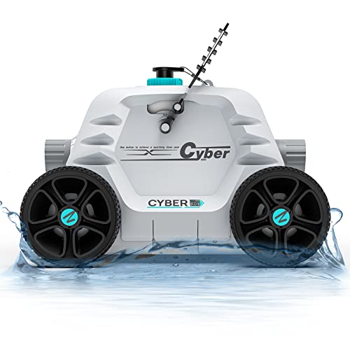
10 Best Automatic Pool Vacuum For Above Ground Pool of 2026 To End Manual Scrubbing

How Much Pool Clarifier Should You Use for Your Pool Size?

How Much Does a Pebble Tec Pool Cost to Build or Resurface?